Geometric design is part of the Sustrans traffic-free routes and greeways design guide. It covers managing speed and providing enough width for all users by presenting minimum design criteria for horizontal and vertical alignments, as well as suitable visibility.
Key principles
- A well-designed traffic-free route will manage speed and provide enough width for all users.
- Minimum design criteria for horizontal and vertical alignments.
- Suitable visibility should be provided to ensure the safety of all users, especially on the approach to roads.
7.1 Design speed
7.1.1
The geometric design of a route will be influenced by the likely speeds at which users will move along it. Visibility along the route, route function and accessibility will also influence geometric design.
7.1.2
Where traffic-free routes are intended to be used as a shared-use facility, interactions between different user groups will be greater, and so speeds are reduced.
On this basis, the concept of design speed becomes less important. Instead, geometric design will be guided by the space required for users to manoeuvre in a way that does not cause inconvenience or delay.
7.1.3
People on bikes are likely to be the highest speed users of traffic-free routes. There are two scenarios where inappropriate speeds are likely to cause an issue:
- Higher-speed users intimidate and jeopardise the safety of lower-speed users, resulting in a reduction in use of the route.
- Speed is inappropriate at interfaces between the route and highway, such as roads and junctions.
7.1.4
The alignment of a well-designed route should encourage appropriate speeds. Providing enough width along a shared-use path can reduce the impact of inappropriate speeds. As there is more space for users to interact and higher speed differentials between users can be accommodated. Where sufficient width cannot be provided, the following measures may help to encourage appropriate speeds:
- Promotion of responsible use of the path, such as a One Path Initiative (Section 3.5).
- The use of signing and surface markings.
- Artwork and other features to create a greater sense of place.
The provision of physical measures to control user speeds, such as speed humps and rumble strips, must be avoided. These features can serve to reduce the convenience and attractiveness of a route and can make a route inaccessible to some users.
7.1.5
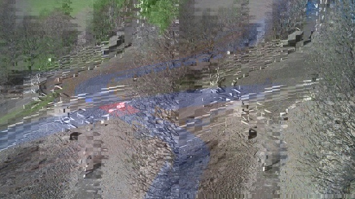
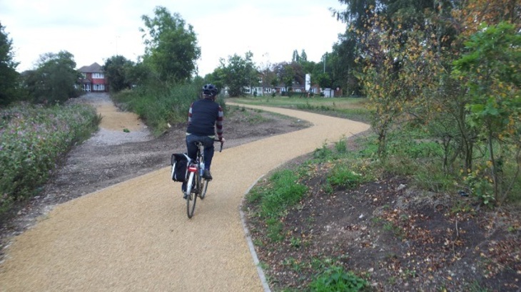
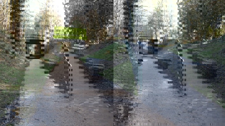
Where it is necessary to encourage slower speeds on approach to a hazard, the preference is to introduce a change in horizontal alignment that will require users to slow down. For example, introducing a 90-degree turn on the approach to a highway interface.
Designers must take care when introducing more severe changes in alignment. It is important that these do not result in people riding bikes or horses having to dismount.
Change in path alignment on approach to highway, Dewsbury, Yorkshire.
7.2 Widths
7.2.1
The width of a traffic-free route is fundamental to its success. Routes should be designed to enable users to move side-by-side, comfortably overtake, and pass other users travelling in the opposing direction.
Widths should also encourage use of the route as a sociable facility, where people can interact as they walk, wheel and ride side-by-side. Widths should be proportionate to the anticipated level, and type, of use.
7.2.2
The effective width of a traffic-free route is considered the ‘useable’ width of the route. Providing a path width that satisfies the requirements of the table below does not mean a suitable effective width will have been achieved.
The table below builds upon the principles of user space requirements and summarises the absolute and desirable minimum effective widths:
7.2.3
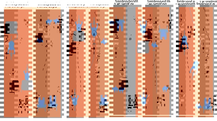
Features located at the side of a traffic-free route can have the effect of reducing effective width. For example, users of a 3m shared use path with fencing either side may ‘shy’ away from the fences. In practice, the ‘shy distance’ can have the effect of offsetting path users towards the centre of the path.
Subsequently, a 3m wide shared-use path with fencing either side may only have an effective width of 2m. Put more simply, only 2m of the path is considered functional by path users, even though there is a 3m wide surface.
Designers should note that shy distances are more applicable to people on bikes and horse riders than other path users. This is mainly due to the risk of handlebars, pedals and stirrups striking vertical features situated alongside the path edge. Thus the effect of shy distances on the effective width of a path needs to be considered against the composition of users of the traffic-free route.
The table below summarises the extra width that can be added to a path to achieve or maintain effective widths. These are applicable where vertical features are present alongside the path.
7.2.4.
The widths provided above are intended as a guide. In some cases, there may be benefits in exceeding these widths, particularly where routes may be used as a safe route to a school. Providing a greater width will also increase level of service and provide passive capacity for future growth in use.
Whilst increasing the widths of routes can provide many benefits for users, it can also be costly to projects. As such, the proposed width of route should be assessed through a Scheme Assessment during the planning stage. This will assist in clarifying what width of route is required to meet the objectives of the scheme and ensure the route is inclusive.
7.2.5
Where a traffic-free route is located next to a road, within the highway verge, it must be separated from the edge of road. The table below summarises the level of separation required.
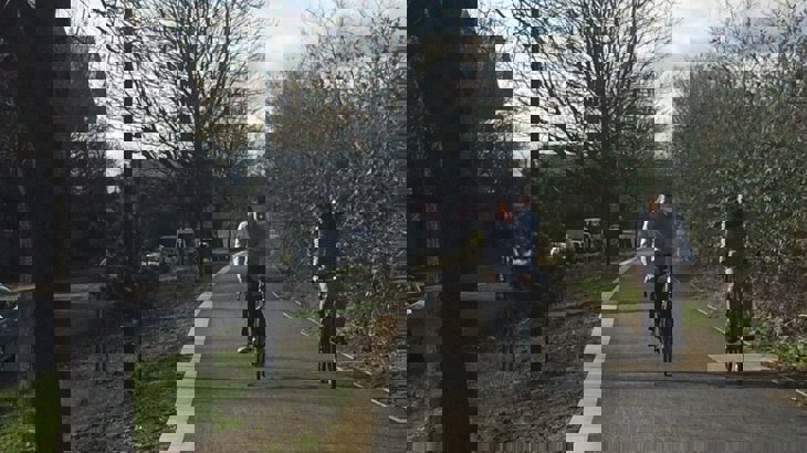
Traffic-free route alongside highway, Millwall Path, London
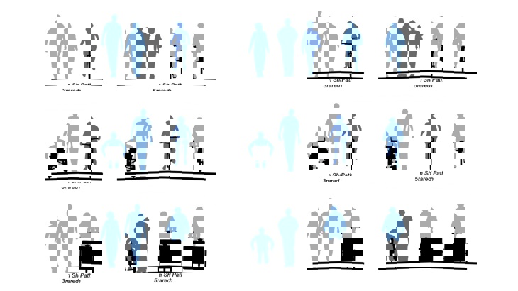
7.3 Typical cross-sections
The following figures illustrate a number of typical cross-sections for traffic-free routes:
7.4 Horizontal alignment
7.4.1
The horizontal alignment of a traffic-free route is fundamental to creating an environment that is inclusive, safe, attractive and memorable. Horizontal alignment will largely be predetermined by the topography of the site, particularly where the route follows a railway corridor or canal towpath.
7.4.2
Depending on the function and user composition of a route, curvature will vary. A route that has a high proportion of commuters using bikes should consider the use of larger radii to ensure that higher speeds can be maintained. In general, routes with a high commuter composition should avoid the use of radii lower than 25m.
Where routes have more of a recreational function, smaller radii may be used to encourage lower speeds. In recreational environments, designers should avoid the use of radii smaller than 15m. Except in specific circumstances.
7.4.3
Where the horizontal alignment is being used to control speeds, such as on the approach to a hazard, a minimum (inside) radius of 4m is appropriate. This will still be negotiable by someone riding a bike but will require a reduction in speed to negotiate the curvature.
Horizontal alignment serves to reduce cycling speeds.
7.4.4
Junctions between paths should have either a 2m radius or a 45° chamfer. This will assist users in negotiating a sharp change in direction. It will also help to reduce conflict and discourage people on bikes from creating informal routes across the verge.
Radius used at junction in route on Nene Way, Northamptonshire.
7.5 Vertical alignment
7.5.1
Local topography can have an impact on the vertical alignment of a route. It is important that designers overcome the impacts of local topography through design.
The design of vertical alignments should ensure that routes remain inclusive, accessible and attractive. The vertical alignment of a traffic-free route should follow the gradients listed in the table below.
7.5.2
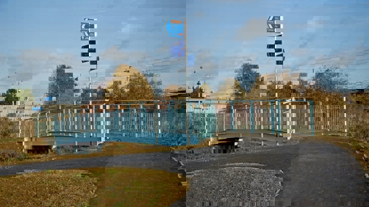
Where existing ground profiles are not excessive, it may be possible to meander or ‘zig-zag’ the route. Whilst this may increase the length of a route, it may reduce the need for earthworks (Section 7.5.3) or retaining structures (Section 10.5). Where this approach to route alignment is adopted, it is common to introduce a set of steps. These provide those walking with a more convenient and direct route up the steeper parts of the existing ground profile.
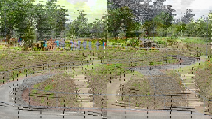
Path along gradient without retaining structures.
7.5.3
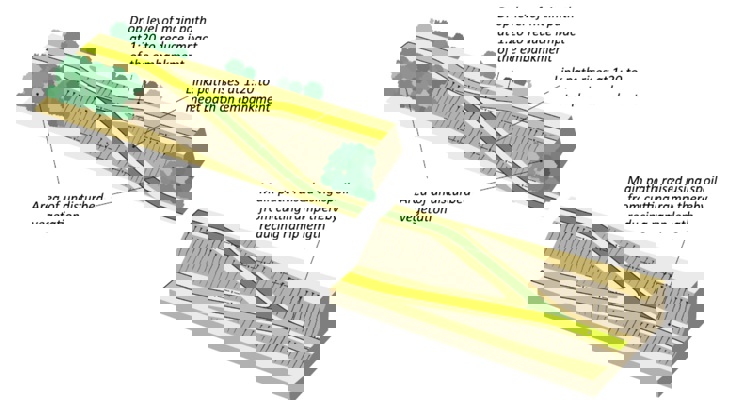
'Cut and fill’ earthworks can be used to overcome irregular or excessive ground profiles. This process involves moving earth from one section of route to another to create a more regular gradient. The figure below provides an overview of how cut and fill can be used to create a more consistent and attractive gradient to users.
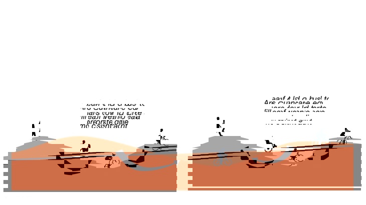
Cut and Fill used on a traffic-free route.
In this example, the black line represents the ideal vertical path profile. This profile overcomes the undulating nature of the existing ground profile. The two highest points of the existing ground profile can be ‘cut’ to ‘fill’ the lowest point in the existing ground profile. In this case, the amount of cut material exceeds the volume of fill material required.
7.5.4
Designers should be aware of the potential for greater speed differentials between users on gradients. This occurrence can affect comfort and safety along routes. Therefore, designers should consider whether more localised width or separation is needed as mitigation. Additional width may also be required on steep uphill gradients. As the effective width of those riding bikes uphill will increase.
7.5.5
Care should be taken to avoid designing a route that has lower sections than the surrounding ground profile. This may result in surface water draining onto the route.
In this scenario, standing water can cause a hazard to users, particularly where the water freezes. Designers should ensure that water sheds from the surface of a path where possible.
This will reduce the likelihood of costly drainage interventions being required post-implementation.
Designers should also note that steep paths could introduce maintenance issues. Where surface water can gather velocity down gradients, it can serve to erode the path surface and verges.
7.6 Ramps and connections
7.6.1
How a traffic-free route connects with a wider transportation network needs careful consideration. Traffic-free routes, particularly those that utilise old railway corridors, canals or rivers, will invariably be required to connect into the highway network.
This requirement presents challenges where, historically, canal towpaths and rail corridors have used structures to ‘grade separate’ the different transport corridors.
Therefore, where routes are planned and designed to use canal towpaths or disused rail corridors, a significant level difference may need to be overcome to provide an ‘at-grade’ interface with the highway network.
Ramp providing access to traffic-free route in Worsley, Greater Manchester.
7.6.2
The vertical alignment of ramps, including the requirement for landings, rest places and handrails should be designed in accordance with the requirements of Inclusive Mobility, DfT 2002. By achieving the requirements of Inclusive Mobility, designers can ensure that traffic-free routes are accessible to everyone.
7.6.3
There may be cases where the location of the ramp and the nature of the route would make the more challenging requirements of Inclusive Mobility disproportionate. For example, where a ramp connects to a canal towpath that incorporates cobbled side arm bridges. In this scenario, wheelers would not be able to use the route even if it could be accessed by a ramp.
Any decision to depart from the requirements of Inclusive Mobility should be documented. Documentation should include an Accessibility Audit / Equality Impact Assessment and Designer Risk Assessment. Under these circumstances, designers must consider how their decisions will affect inclusivity.
7.6.4
The construction of a ramp may need retaining measures. These can increase the cost of a scheme and need additional land to be acquired. The cost of introducing retaining measures needs to be considered against the extra cost of providing a longer route that follows natural ground gradients and does not require retaining measures.
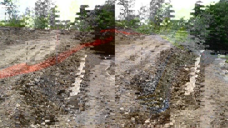
Crib wall Construction on Padiham Greenway, Burnley, Lancashire.
7.6.5
To reduce the likelihood of non-compliant ramp gradients, it may be possible to locally adjust the level of the traffic-free route to decrease the level difference, as shown in the figure below:
7.6.6
Where providing ramped access is not possible, consideration should be given to relocating the access point. Access points could be moved to a position where there is less level difference, or there is space to construct a ramp. The benefit of accessibility to all users is likely to outweigh reductions in directness.
7.7 Visibility
7.7.1
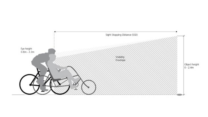
When designing a traffic-free route it is important to provide enough forward visibility. This will ensure that all users are aware of changing situations ahead. Providing enough forward visibility is relevant to those users travelling at greater speeds. This is termed stopping sight distance (SSD) and is the distance travelled in the time taken to react and stop.
Sight distance in motion (SDM) is the distance that someone needs to be able to see ahead when moving to feel safe and comfortable. Typically, this is the distance covered in 8 to 10 seconds whilst moving towards an object.
7.7.2
Traffic-free routes should be designed to achieve the SSD and SDM values set out in the table below. These distances should be provided within the envelope of forward visibility shown in the figure below. The SSD values in the table apply to a level route with a sealed surface, at the design speeds shown. SSD will increase at greater speeds, for downhill gradients and poor surface conditions. Poor surface conditions will include wet and icy surfaces as well surfaces where leaves are present. SSD on unsealed surfaces should be increased by 50%.
7.7.3
Where a traffic-free route joins a road or another route, adequate visibility between users on each route must be provided. Designs should ensure that visibility within the envelope shown in the figure below is not obscured.
This visibility envelope is determined by the speed of traffic (motor or people on bikes) on the major arm of the junction. It assumes that the traffic-free route adjoins a highway network. Although the principles would be applicable to a junction with another traffic-free route.
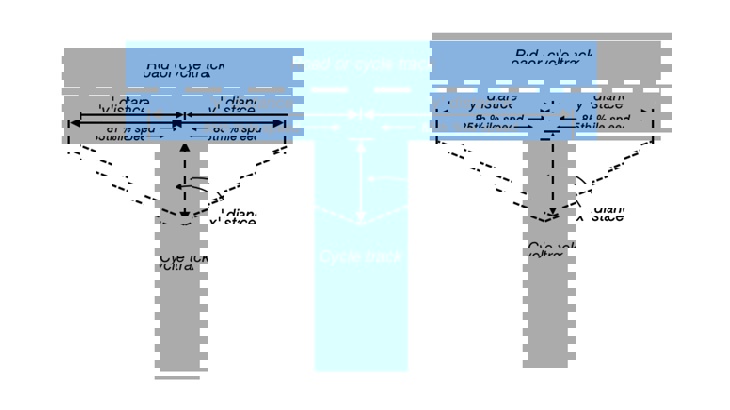
7.7.4
An ‘X’ distance, measured from the give-way line or edge of the major arm, of 4.5m should be used where possible. This will ensure that route users have adequate time to determine whether they need to stop at the junction.
This distance may be reduced to 2.4m and to 1.0m as an absolute minimum where cycle approach speeds are low and the approach geometry encourages a reduction in speed on the traffic-free route. ‘Y’’ distances will be determined by the type and speed of the road environment.
Typical ‘Y’ distances are shown in the table below:
7.7.5
In circumstances where traffic-free routes adjoin the strategic highway network, achieving the visibility requirements of the Design Manual for Roads and Bridges (DMRB) will be required.